
rpic ships a native library of 79 circuit elements —
a from-scratch re-imagining of J. D. Aplevich’s celebrated
circuit_macros, written in pure pic (no m4). Load it with
circuits = TRUE, or from inside the source with
copy "circuits"; both are equivalent:
library(rpic)

rpic_svg('A:(0,0); B:(2,0)
resistor(A,B)', circuits = TRUE)

rpic_svg('copy "circuits"
A:(0,0); B:(2,0)
resistor(A,B)')
All figures below were pre-rendered with the code shown.
Two-terminal elements
resistor, capacitor, inductor,
battery, diode, led,
fuse, sources, meters… — each draws between two named
points, connecting wire included. A classic RLC loop:
rpic_svg('
SW:(0,0); NW:(0,1.2); NE:(2.4,1.2); SE:(2.4,0)
battery(SW,NW); resistor(NW,NE); capacitor(NE,SE); inductor(SE,SW)
dot at NW; dot at NE; dot at SE; dot at SW
', circuits = TRUE)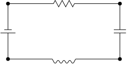
Labels — with TeX math
Circuit figures traditionally carry math labels; combine the library
with texlabels:
rpic_svg('
A:(0,0); B:(1.4,0); C:(2.8,0)
resistor(A,B); "$R_1$" at 0.5 between A and B + (0, 0.35)
diode(B,C);   "$D_1$" at 0.5 between B and C + (0, 0.35)
', circuits = TRUE, texlabels = TRUE)
Logic gates
Gates take a center point and export their terminals as variables
(gA_x/gA_y, gB_…,
gY_…):
rpic_svg('
P:(0.5,0); and_gate(P)
Q:(1.9,0); nand_gate(Q)
R:(3.3,0); xor_gate(R)
"AND" at (0.5,-0.55); "NAND" at (1.9,-0.55); "XOR" at (3.3,-0.55)
', circuits = TRUE)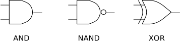
Multi-terminal devices
Transistors and op-amps also export their terminals as variables
(gBase_*, gColl_*, gEmit_*), so
wiring attaches precisely:
rpic_svg('
npn((0,0))
line left 0.3 from (gBase_x, gBase_y); "B" rjust at last line.end - (0.04, 0)
line up 0.25 from (gColl_x, gColl_y); "C" above at last line.end
line down 0.25 from (gEmit_x, gEmit_y); "E" below at last line.end
', circuits = TRUE)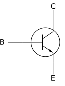
In R Markdown / Quarto
Register the knitr engine once and write pic directly in chunks, with
circuits (and texlabels, scale)
as chunk options:
```{r, eval = FALSE}
rpic::rpic_register_knitr()
```

```{rpic, circuits=TRUE, scale=2}
A:(0,0); B:(2,0)
resistor(A,B)
```
The full element list lives in the library source; a gallery of 48 circuit_macros figures rendered by the same engine is in the engine repository.